Replacing RF patch panels with a software-controlled RF switch matrix
Replacing RF patch panels with a software-controlled RF switch matrix
One of the most common issues facing RF lab managers is the cost of setting up various RF testing scenarios, executing the tests, and then tearing down those same setups. Not only is this tedious, time-consuming, and manual labour, it also creates excessive stress and strain on expensive RF components.
To set up a given RF test, the lab manager must ensure that the appropriate RF signals are routed to the right test station. When they reach the test station, these RF signals are passed through a set of variable attenuators before terminating to an RF shield box. The tester controls the attenuators to simulate the desired RF environment inside the shield box.
The RF rat’s nest
Routing RF signals to different test stations is usually done by disconnecting and reconnecting various cables to different ports at a large patch panel located near the RF sources. If a signal is required by more than one test station, RF splitters are used to distribute the signal. This rapidly creates a cabling mess that is often poorly labelled and documented. Depending on the number of times the RF signals are split, those signals may have very different levels when they reach various test stations, which can complicate the testing procedure.
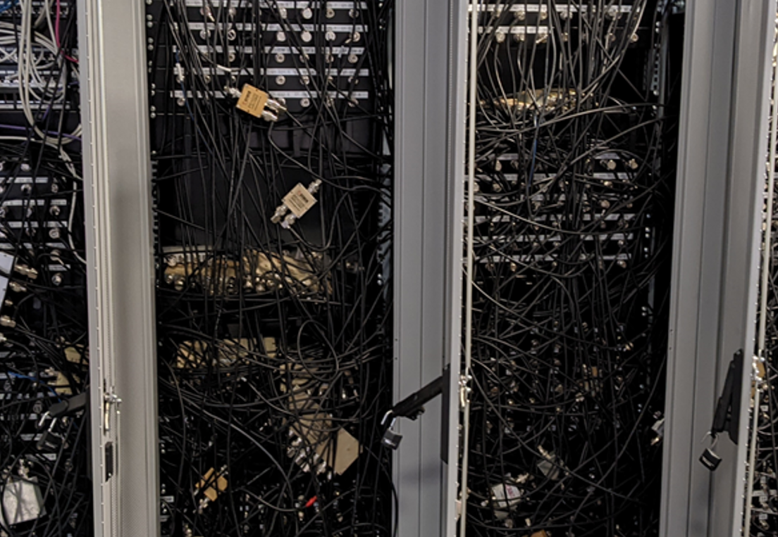
It can take hours to reconfigure the signal routing for a desired test. Existing cabling must be traced to see how it is being used. At the same time, making patching changes can disrupt other tests in progress. Every time a test is configured, the RF signal routing environment changes, and this means the tests are no longer reproducible.
Executing the tests also takes significant effort. The tester must individually control the variable attenuators locally at their test station. This is highly manual and difficult to reproduce from test to test.
The cycle begins again after the tests are completed. RF cables are disconnected, re-routed to other ports and reconnected, which introduces RF connector durability issues from excessive wear and tear. The use of splitters places additional stress and strain on the RF cable connectors and can cause signal degradation and leakage. This will affect testing results, introduce lengthy debugging times, and expensive cables will need to be replaced.
Automating RF signal distribution and attenuation control
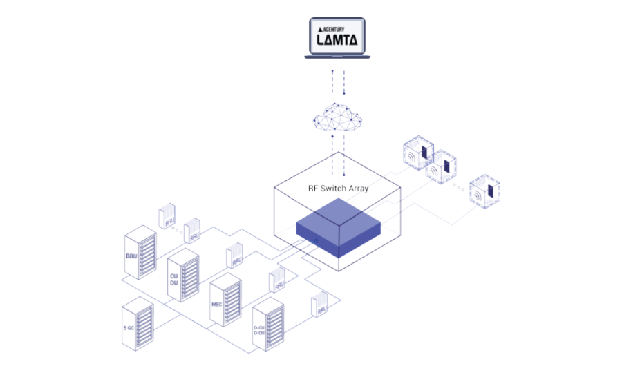
LAMTA’s orchestration software solution replaces the RF patch panel and individual splitters with a software-controlled RF switch matrix. All RF sources are connected to the matrix inputs and each matrix output is connected to a different test station. All cabling is done once, and cabinet doors can be closed and locked. Since they aren’t being manipulated frequently, they will not need replacement as often, and the RF environment never changes between tests.
Save time and money with LAMTA
LAMTA’s orchestration software solution replaces the RF patch panel and individual splitters with a software-controlled RF switch matrix. All RF sources are connected to the matrix inputs and each matrix output is connected to a different test station. All cabling is done once, and cabinet doors can be closed and locked. Since they aren’t being manipulated frequently, they will not need replacement as often, and the RF environment never changes between tests.
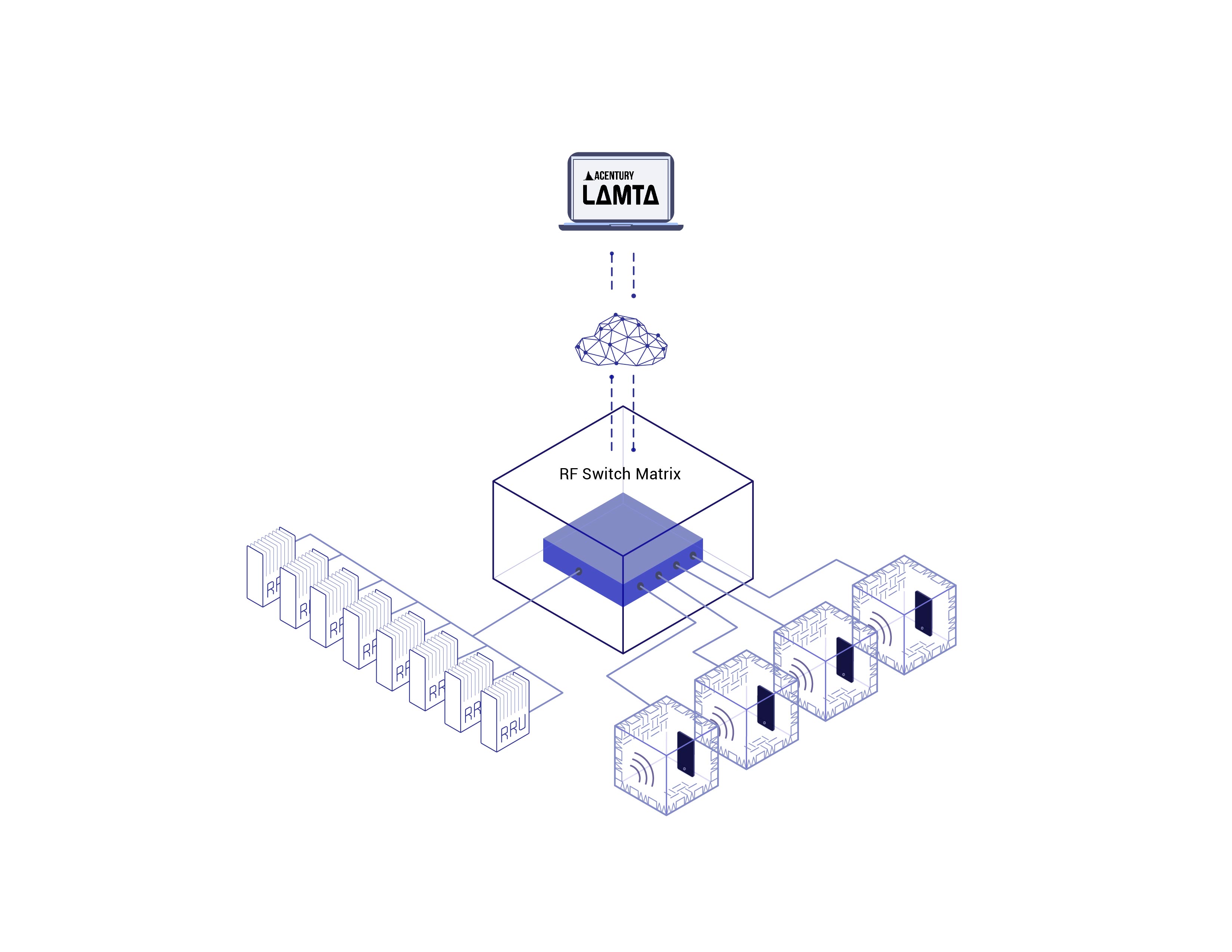
LAMTA software controls the signal routing, splitting, combining and attenuation inside the matrix. The matrix can connect any combination of inputs to any combination of outputs. No manual patching is required; further, the right combination of RF signals can be sent down a single RF distribution feed to each test station.
Through the switch matrix, LAMTA also controls the mixing and attenuation of the signals on that single feed. This means variable attenuators are not required at each individual test station and the attenuation can be remotely controlled by the tester.
Since the switch matrix shares all RF signals equally among all test stations, all signal levels are balanced and stable. In this way, LAMTA allows tests to be perfectly repeated, hundreds or thousands of times as needed.
Have a question or comment?
We'd love to hear it. Fill out our General Inquiry Form or reach us directly at: info@acentury.co
CONTACT US